|

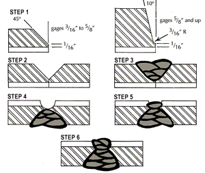
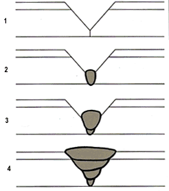
Design considerations may render welding from both sides impossible. In this case, welding can be accomplished from the cladding side only as shown in Figure 5. While more demanding and requiring more control of dilution, usually with higher alloy consumables (overmatching), functional, corrosion resistant welds can be produced. It is important to note that during this process, care should be exercised to avoid contaminating the initial passes into the backing with the cladding, particularly with the high alloys, so as to avoid producing brittle intermetallics. This is easily accomplished by proper joint design or sufficiently stripping back the cladding.
Light thickness clad plates are usually most economically welded using full alloy welds. This has been particularly true with the high performance clads used in flue gas desulfurization applications where the advent of the new generation of synergic feedback "GMAW" equipment has proven to be a major advancement in the production of low heat input welds necessary to reduce dilution and produce sound, corrosion resistant welds. GTAW has also been used for these purposes, though it is usually less efficient. In these cases, the sequence of welding may involve the cladding side first. Welding of straight chromium (400-series stainless) clad, nickel clad, copper and copper-nickel clad steels involves slightly special considerations, but are readily weldable like the 300-series stainless clads. Consult BLP to discuss your special needs. Stress relieving may be required by the design specifications or as a result of the ASME Pressure Vessel Code and would be based on the thickness of the backing steel. The 400-series stainless clads should be stress relieved in the range of 1100�F--1350�F with consideration given to the backing properties. The 300-series stainless steels can be subject to carbide precipitation during stress relief, but this can be minimized by the use of extra low carbon or stabilized grades. Preheating before welding is a requirement determined by the nature of the backing steel. A302, A204 and A387 are some of the common alloy steels requiring preheating. Preheating may also be considered for heavy thickness clad plate or for highly restrained joints. |
||||||||

Bethlehem Lukens Plate Products
If you have any questions or comments, please Contact Us
�1999, Bethlehem Steel Corporation