| |

Customer Corner • Products • Packaging Manual •
Quality • QuickPLATE™
Steel Inventories • Technical Support •
Sales Offices •
Facilities
Cross Frame Connections:
All plate girder bridges have connections which attach the required transverse cross frames to the longitudinal girders themselves. It is common to connect these cross frames to the transverse web stiffeners in order to optimize the use of materials. AASHTO requires that these vertical plates, which connect cross frames to the girder, be rigidly connected to both the top and bottom flanges. It is this rigid connection that creates concern when attached to a tension flange.
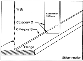
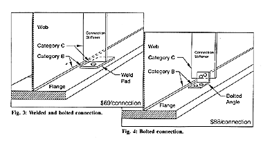
There are many ways to provide this rigid connection. Figures 2, 3 and 4 show three common methods along with their associated cost (courtesy of Duane K. Miller, The Lincoln Electric Company; and AISI). These are among the most simple, economical connections. Any details that are more complicated add cost but no additional structural value.
The most cost effective means of providing the required rigidity is by fillet welding the stiffener to the flanges (Fig. 2). This creates a Category C fatigue detail at the flange subject to tension stress or stress reversals. Some engineers have a reluctance to use this detail because it does weld to the tension flange. However, research conducted in the development of the fatigue categories found that welding to the tension flange did not create any problems under the Category C stress ranges. In many cases, designs that satisfy strength and deflection criteria, result in stress ranges that also satisfy Category C. A Category B detail should not automatically be used for attaching a connection stiffener to the tension flange.
For example, in bridges carrying a Case II load frequency, and designed to satisfy strength criteria, the Category C stress range will generally not be exceeded. Likewise, for Case I load frequency, in structures designed for overload or permit vehicles, or having simple spans, Category C stress ranges will generally not be exceeded. Another common design practice is to use HS25 live loads for strength criteria, but to use HS20 live loads for fatigue analysis. Again, this will generally result in designs for which Category C stress ranges are satisfied. In all these cases, a simple welded detail is most cost effective.
At those points where these stress ranges are not satisfied, two options exist. The first is to use a Category B detail. This can be done by providing a pad assembly bolted to the flange and welded to the stiffener (Fig. 3). A fully bolted connection angle (Fig. 4) could also be used, although it costs $18-20 more per connection than the welded and bolted connection.
A second alternative is to reduce the computed stress range by increasing the section properties in specific locations, thus allowing the use of Category C fillet weld at all points along the girder length. A comparison of the cost to upgrade the detail versus upgrading the section indicates that it is generally more economical to use a limited number of Category B details than to increase the section.
Conclusions:
- It is never economical to use Category B details for the entire length of the girder. Using Category B details when Category C details are adequate adds cost but not value.
- Use a simple fillet weld to attach the stiffener to the tension flange wherever the Category C stress range is not exceeded.
- Category B details should never be used to attach the stiffener to the compression flange.
- Use the least complicated (most economical) Category B detail only in those locations where Category C is exceeded.
- Check to see if it is more economical to increase the girder's section properties than to use a limited number of Category B details throughout the girder length.
- For overload or permit vehicle applications, strength will generally control the design, thus allowing the use of Category C details throughout the girder length.
- Maintain diaphragm spacings close to the maximum allowed. This minimizes the total number of rigid attachments at the flanges.
Economics of Girder Spacing:
The cost of a steel superstructure erected depends on three items.
- The cost of the plain mill material
- The cost of fabricating the material
- The cost of erecting the fabricated girders
Both fabrication and erection, however, are dependent on the number of pieces to be handled in the shop and in the field. Generally speaking, anything that reduces the number of pieces also reduces the overall cost. Wider girder spacing is one of the major factors in reducing the pieces to handle, ship, erect, paint, inspect and maintain.
The following information was developed using the Bethlehem plate girder optimization program. This unique program optimizes girder designs on the basis of fabrication cost, not girder weight. It considers material costs as well as the basic fabrication costs of stiffener attachment, flange and web splices, web to flange welds, shear connectors, and cleaning and painting. The program was used to compare the relative costs of 9'-8" and 12'-6" girder spacing for the sample bridges. Table 1 shows both the relative and actual cost differentials using a base price of $0.65/lb. For the fabricated girders.
Girder Cost Comparison:
| Bridge |
Cost Index |
Cost ($) |
Savings ($) |
120'
Simple Span
-5 GR @ 9'-8"
-4 GR @ 12'-6"
|
1.08
1.00
|
94,000
87,000
|
7,000
|
100'-140'-140'-100'
Continuous
-5 GR @ 9'-8"
-4 GR @ 12'-6"
|
1.09
1.00
|
383,000
351,000
|
32,000
|
150'-200'-200'-150'
Continuous
-5 GR @ 9'-8"
-4 GR @ 12'-6"
|
1.09
1.00
|
726,000
666,000
|
60,000
|
225'-225'-275'-225'-225'
Continuous
-5 GR @ 9'-8"
-4 GR @ 12'-6"
|
1.06
1.00
|
1,709,000
1,620,000
|
89,000
|
In addition to the obvious savings in main materials, there are other less obvious economics also. By eliminating one row of girders, we have also eliminated a row of diaphragms, 2 lines of tension flange connections, and a line of bearings. We have, however, added some cost to the slab due to thickness increase and to the deck forming. Table 2 shows the magnitude of savings available using wider girder spacings.
Superstructure Cost Comparison:
| |
|
Costs ($) |
|
|
| Bridge |
Girders
($0.65/#) |
Cross
Frames
($525 ea.) |
Cross Frame
Connections
($6 ea.) |
Total |
120'
Simple Span
-5 GR @ 9'-8"
-4 GR @ 12'-6"
|
94,000
87,000
|
12,600
9,450
|
576
432
|
107,176
96,932
10,244 |
100'-140'-140'-100'
Continuous
-5 GR @ 9'-8"
-4 GR @ 12'-6"
|
383,000
351,000
|
48,300
36,225
|
2,208
1,656
|
433,508
388,881
44,627 |
150'-200'-200'-150'
Continuous
-5 GR @ 9'-8"
-4 GR @ 12'-6"
|
726,000
666,000
|
69,300
51,975
|
3,168
2,376
|
798,468
720,351
78,117 |
225'-225'-275'-225'-225'
Continuous
-5 GR @ 9'-8"
-4 GR @ 12'-6"
|
1,709,000
1,620,000
|
111,300
83,475
|
5,088
4,056
|
1,825,388
1,707,531
117,857 |
Overall Conclusions:
- Minimize the number of girders in a cross section-use spacings of 12' or greater when possible.
- Space cross frames as far apart as practical, considering constructibility.
- Use Category B connections to tension flanges only where the stress range exceeds that of Category C.

|


